 |
Shaking forces of twin engines Vittore Cossalter |
| |
Shaking forces of twin engines Vittore Cossalter |
A little theory
Let us consider the schematic
drawing of a twin engine as shown in figure 1.
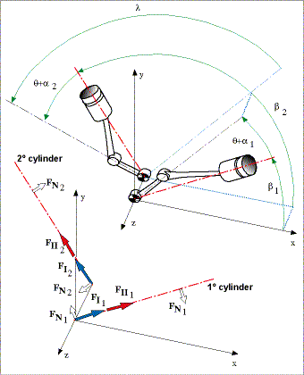
Fig. 1 Scheme of twin engines and shaking forces
As is well known, the shaking forces are the following:
where:
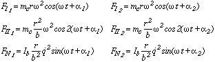
The components of the primary inertia force (first order) are:
It should be noted that the forces FN are extremely reduced if compared with primary and secondary inertia forces.
This force rotates in the same direction as that of the cranks and traces an ellipsis or a circle in the x-y plane, depending on the amplitudes and phases of the two components.
Complete balancing is possible only if the two components have the same amplitudes and a phase angle equal to 90°. To reach this condition, the angle between the two cranks must respect this equation:
In this case, the simple addition of a mass in opposition to the primary inertial force is enough to obtain a complete balance. If the polar diagram of the primary force is an elliptical curve, the balance is only partial.
The components of the secondary inertia forces are the following:
These components represent a force, generally with non-constant amplitude, rotating with a velocity double that of the cranks.
The primary and secondary forces are not in the same plane. For this reason, unbalanced couples will be set up which tend to rotate the engine around an axis perpendicular to the z axis. The values of these couples can be determined by multiplying the force by the distance between the two cylinders.
Examples
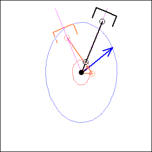
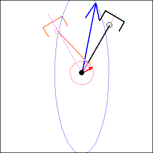
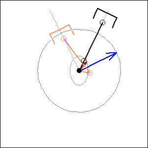
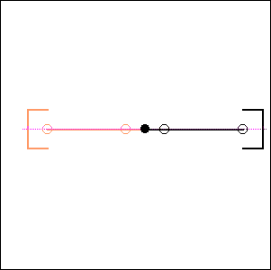
In the following examples, the blue arrow represents the first inertia force and the red one the second inertia force.
 |
45 degree
cylinder angle, 75 degree crankshaft angle |
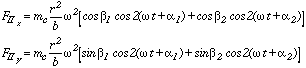
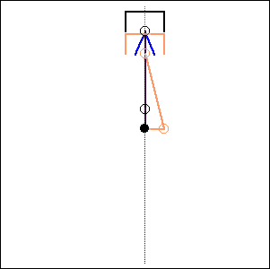
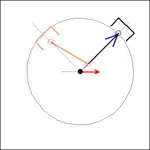 Fig. 3. 90 degree cylinder angle, 0 degree crankshaft angle (like Moto Guzzi) |
 |
. 90 degree
cylinder angle, |
 |
60 degree
cylinder angle, |
|
Fig. 6. 52 degree cylinder angle, 76 degree crankshaft angle ( like Honda Transalp) |
|
Fig. 7. 180 degree cylinder angle, 180 degree crankshaft angle ( like BMW boxer) |
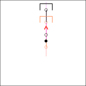 |
Fig. 8. 0 degree cylinder angle, 180 degree crankshaft angle ( like Laverda 750) |
 |
. 0 degree cylinder
angle,
|
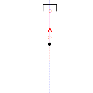 |
Fig. 10. 0 degree cylinder angle, 0 degree crankshaft angle |